Sunday, 29 March 2015

Hand-drawn Process Flows: Part 3 - More Shapes

A Free Document Productivity Tool For Visio

This post complete hand-drawn process flow shapes. With these tools you can complete model simple process flows using Visio's swimlane template. 

The Hand-drawn post series looks like this:

  • Part 1 - Introduction - How the hand-drawn look is created. Shows all shapes.
  • Part 2 - Basic Shapes - Good for most process flows.
  • Part 3 - More shapes - For more advanced models.
  • Part 4 - Building a hand-drawn template.
  • Part 5 - Quick posts - Three more great hand-draw shapes for process flows.


The Group Shape


The group shape is a standard BPMN shape that defines a set of processes.


The shape can be sized to surround other shapes.  It uses the standard randomizing routines to create the hand-drawn look.

The Data and Output Shape


The data shape is part of the BPMN set and can be used to signify data, information in many formats.  The output shape is not standard BPMNN shape. It is a bit old school these days, but almost everyone viewing it immediately gets the idea.


I had a lot of fun building these shapes.The data one really shows the technique of drawing a right angle.  If you draw it with two lines, Visio wants to smooth the line into a wide curve.  To counter this, you have to draw a line back into the corner before starting the next side.  This gives you a tight corner while still preserving the curve smoothing needed for the long sides.


The output shape required formal curve definitions to get the sweeping curves at the bottom. It uses the ArcTo geometry method which uses start, and end coordinates and a measure for the arch height.


The SmartConnector 

The SmartConnector joins process shapes and is based on the standard dynamic connector .  It includes optional message and activity shapes which can be used to convey meaning
There has been a surprising amount of refinement put into the connector.  It isn’t randomized because I need the dynamic smarts for retaining connection as shapes move.  However I have coloured it to match the hand-drawn standard, and most folk don’t seem to notice.

The text block is positioned just to the right of the start position.  I find this is the most likely location


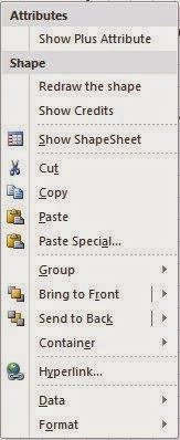
When you right click you can select Message or Gears.


When either of these is selected, the shape offers a choice of locations at 25%, 50% and 75% from the start. As the length of the line changes, the icons move accordingly


The Note Box


The note box is useful for annotating diagrams. I have used a standard hand-drawn rectangle for the outline and the regular comic sans font.  


The box will also automatically resize as you add content.  It extends down while holding the width constant and demonstrates some useful Shapesheet text control attributes.

Other Shapes

I have added a number of other shapes to this stencil which will be the subject of subsequent posts
  • Swimlane and Pool Edge – These are part of the standard Visio cross functional flowchart tools. I have adapted these for hand-drawn diagrams
  • SmartAudit – This shape gives date, version and author information. It fits nicely into the cross functional flowchart and is linked to the right hand edge so that as the boundaries of the diagram move, so does the auidit box.
  • SmartAnnotation – This annotation tool remains linked to the parent shape is attached to, when the parent moves, the annotation does too.  It’s a real time saver.
  • Speech Bubble – I’ve lifted this from the Visio Guy – Take a look at his site for more fun shapes.
  • Other hand-drawn shapes –I’ll add a triangle shape and a hand-drawn line to the template shortly.

Downloading the shapes

You can download the stencil with these shapes from the Visio Downloads page here.

I am keen to hear how you find the shapes, so please leave a comment.

Monday, 8 December 2014

Hand-drawn Process Flows: Part2 - Basic Shapes

A Free Document Productivity Tool For Visio

This post describes the basic hand-drawn process flow shapes: Start, End, Task and Gateway. With these tools you can model simple process flows using Visio's swimlane template. 

The Hand-drawn post series looks like this:

  • Part 1 - Introduction - How the hand-drawn look is created. Shows all shapes.
  • Part 2 - Basic Shapes - Good for most process flows.
  • Part 3 - More shapes - For more advanced models.
  • Part 4 - Building a hand-drawn template.
  • Part 5 - Quick posts - Three more great hand-draw shapes for process flows.

The Task Shape

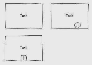
The task shape is a basic hand-drawn rectangle that is the basis for many of the other shapes.

There are two variants on the basic rectangle that you can control by right clicking the shape.

Collapsed indicates that there a detailed definition of the process task. I use this when the process is in another page in the Visio document.  

Loop indicates that the process is repeated.


I don't use the variants very often, they can be too BPMN specific for some audiences, but you might find them useful.  

The text box uses Comic Sans for a  hand-drawn look, and the text box itself is bounded by the shape. I decided not to let the text box expand the size of the box.

Design Note:
Each of the variant icons is a separate geometry in the shape. If you follow the ShapeSheet links, you'll see how clicking the action entry reveals and hides the icons. The user section of the shape has sizing constants that mean the icons grow or shrink as the shape size changes.


The Gateway Shape


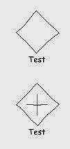
The gateway shape has a similar geometry to the task shape in that it is a rectangle with the same 3 section randomised side as the task shape.  


There is one variant, the plus sign, which is very BPMN specific, so use appropriately.  


Design Note: 
If you look at the geometry of the main shape, you will see a special "Line to" the previous geometry point.  This is an important point.  Without line rounding, Visio "draw" conventional rectangular shapes, however, I need line rounding to smooth out the randomising.  This has the effect of rounding the shape corners too.  By adding a specific line back to each corner, the rounding is cancelled out.

The geometry of the plus sign has User values to control the gap between the sigh and the corner of the shape.  I've added the hand-drawn effect to the plus sign too.


The Start Shape

The start shape is the most complex shape in the palette, it is actually four separate shapes grouped, one for the main shape, one for the intermediate inner ring, and one each for the timer and message icons.

The intermediate icon can be used with or without the other icons, but you can have one one of either timer or message. 


Design Note:
Since I'm using randomised shapes, the challenge is to ensure the inner shapes dont cross over into the outer. To solve this I drew the four shapes at the right size separately. I then created a group with just the main shape ("Start a Group"), then added the first inner shape to the group ("Add to Group"). The inner shape is subordinate to the main, so I could refer to the main shape's randomised values, this means that you get the exact same outline, only a little smaller.

The clock face is easily the most complex shape, I needed a refresher on my high school trigonometry to get the hour marks pointing towards the centre, and each the same length.

The message icon is based on the rectangle with the extra angle.


The End Shape


The End Shape is a cut-down start shape.  I left the message icon, but removed the Timer.

The additional thickness of the outline means that I had to tweak the sensitivity of the "wavy-ness" down a little for this shape.


Downloading the shapes

You can download s stencil with these shapes from the Visio Downloads page here.

See the following post for more hand-drawn shapes.

I am keen to hear how you find the shapes, so please leave a comment.

Sunday, 7 December 2014

Hand-drawn Process Flows - Part 1 - Introduction

A Free Document Productivity Tool for Visio

This post introduces a set of process flow shapes in a "hand-drawn" style. 

Producing process models using these shapes helps convey a “work-in-progress” feel that signals informality and encourages discussion. 

The are suitable for simple flows aimed at a business audience, who should be able to follow them with minimal understanding. I often use them to confirm conversations and draft processes before recording them formally once I have got agreement.

You can use them to prepare standard flowcharts, but they are ideally suited to swim-lane diagrams using the standard Visio template.  See the following example:


The main shapes are a task, start and end circles, and a decision or gateway diamond.  They have a wavy appearance around the edges as if drawn by hand. 

The shapes are actually a subset of the full BPMN suite. Limiting the BPMN
palette reinforces the the “simplicity” intent, but if you right click on many of the shapes you'll see additional display options which provide more BPMN-like models.  In the example above you can see the collapsed and loop icons, and the timer.

Each shape is subtly different from the others of its type. I have optimised the "wavy-ness" of each shape for scale and line thickness, but sometimes the shape may look too extreme. If you right click on the shape you will see the option "Redraw Shape". When this is click,ed a new randomised outline is generated.


Here is a sample of each of the shapes


Inspiration

I liked the idea of hand drawn shapes, several of the major process modelling

Sunday, 23 November 2014

Taking Stock

A Free Document Productivity Tool for Word

I have been working on some process documentation in the past few weeks, so I'll give the Word macros a break and post some of the Visio tools that I have developed over the last couple of years.


Hand-drawn Process Flow Shapes

My first Visio post will be a set of process flow shapes with a funky hand-drawn look. This signals informality, and promotes discussion. I think they are fun to use too.

The shapes can be used for flowcharts, but there are extensions so you get a decent subset of the BPNM shape palette with shape variants you can switch on and off.

Other Upcoming Visio Posts

My Visio tools provide efficiency improvement features that you can use everyday.  They are especially useful for people laying out process flows, context diagrams and preparing simple graphic designs for summarising business issues and solutions.

The Visio posts coming soon are:
  • Hand-drawn process flow shapes - stencil and template
  • SmartAlign - Enhanced Horizontal and Vertical alignment tools
  • SmartSize - An smart tool for consistently sizing shapes
  • SmartLink - Connector link tools used when adjusting process flows

I'll also be adding a range of smart shapes for reducing the effort when BPMN diagrams - I'll publish a stencil and template for these too.

I also regularly use a set of page re-size and layout tools which I'll also publish.

Word Tools

I have not finished with Word, I have the following tools yet to publish.  Let me know if you want any expedited.  The upcoming tools are:
  • SmartAnnotation - Enhanced annotation
  • SmartBrowse - Extensions to the standard browse tools for managing reviews.
  • Advanced document review tools for managing editing tasks
  • Advanced Table formatting - quickly inserting tables, formatting subsections and making tables consistent across the document.
There are one or two other small items which I use a lot - things like cleaning up double spaces, dropping bookmarks, 

SmartTable Insert Update

A Free Document Productivity Tool for Word

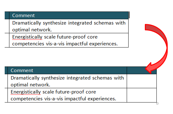
I have added logic to the SmartTable Insert tool to improve the way Word inserts columns

When Word adds columns, it adds them with the same size as the column at the start point.  

I find that inconvenient, especially if auto resize is switched off, the new column can be created off the width of the page.


The SmartTable Insert routine has been altered to add a modest sized new column to the right if the cursor is just outside the first row. 


To insert a column, make sure the cursor is just outside the table at the first header row.


The new table is of modest size, not the monster sized column that I usually get.


Summary

This is an update to SmartTable Insert.  The latest copy of all Tool code can be found in the Downloads tab.

SmartTable Number Update

A Free Document Productivity Tool for Word

There have been a number of improvements to SmartTable Number, the tool that renumbers and tidies tables in Word.

The highlights are:
  • Ability to handle multi-row headers.
  • Suffix codes e.g “7a, 7b, 7c..” added for rows that follow from the one above.
  • Continue numbering from a previous table.

Handle Multi-row headers

SmartTable Renumber is designed to start numbering from the first row after the header. Previously, only single row headers were supported. Having worked on some complex tables lately, I added logic to handler multi-row headers.

You can now use the “Repeat Header Rows” option in the Table Layout tab to define multi-row headers. Numbering will start from the first regular row after the header.

Using the "Repeat Header Rows" sets a flag on each header that ensures the header gets repeated on each page.  The numbering routine tests for this flag and skips header before starting to assign numbers.

Suffix Codes

The routine now numbers rows that have a blank cell in column 2.  It does this by appending “a, b, c…” to the previous row number.  


In this example, since there is no text in column two, the routine has added the suffix a, b, c... to the previous row. 


To switch this on, a new entry in the table control list has been added.  A value of S adds this suffix.  If a value of “N” is entered, rows with a blank column 2 are not numbered.


I needed this logic to handle some complicated tables where the second cell was sometimes a header for several rows that follow.

Continue numbering from a previous table

To continue numbering from the previous table type ”-1” in the first number cell and then select SmartTable Number.

The routine will go to the previous table and get the last number (and prefix, if any) from the previous table and continue numbering.

The “-1”refers to the number of tables to go back, If you type “-2”, the routine will get the number and any prefix from the table before the previous one.  This allows me to insert small tables between the main numbering sequence


In this example -1 has been added to the first row of the second table.  


After selecting SmartTable Number, the numbering from the previous table has been copied down.


I needed this logic to handle several tables that needed to have a common numbering. 

The routine is not smart enough to automatically renumber a series of tables, you have to do them one at a time. This isn't a limitation of coding, its more of a limitation in the way Word works. There are no spare fields in the table properties to permanently store the relationship between tables, this makes building repeatable process tricky.

Summary

This is an update to SmartTable Number.  The latest copy of all Tool code can be found in the Downloads tab.

Sunday, 28 September 2014

Select List

A Free Document Productivity Tool for Word


This tool selects an entire bulleted or numbered list ready for further editing or formatting.

It is based on code used by SmartPunctuation, a tool that automatically punctuates a bulleted or numbered list.


The instructions are relatively simple, place the cursor anywhere in the list and select the shortcut key.  The list will then be selected.


The key selection routine used for Select List is also used for by SmartPunctuation. The routine has a number of special features

Handle bulleted lists inside tables.